
In one line: a stability chamber holds a fixed temperature and relative humidity by running conditioned air in a continuous loop past a heater, a refrigeration coil and a humidifier, with a PLC trimming each one against sensors mounted in the return air.
The reason a stability chamber in pharmaceutical industry laboratories exists is not the hardware, it is the storage condition it has to hold. ICH Q1A(R2) defines seven storage conditions for drug products[1], and the chamber is qualified against whichever one your protocol names. This page gives the seven conditions with their tolerances, the condition WHO records for India, what mapping and calibration are actually required by (and what is only convention), and an adaptable operation and monitoring SOP.
What a stability chamber in pharmaceutical industry laboratories must actually hold
Two numbers separate a stability chamber from a laboratory incubator or an environmental cabinet: the temperature tolerance and the relative humidity tolerance written into the storage condition. ICH Q1A(R2) writes them into the condition itself, so 25 °C ± 2 °C / 60 % RH ± 5 % RH is not a set point plus a manufacturer’s accuracy claim. It is the band the samples must stay inside for the whole study[1].
The regulatory requirement on the equipment is deliberately short. WHO’s stability annex says only that “the equipment used should be capable of controlling the storage conditions within the ranges defined in these guidelines” and that “the storage conditions should be monitored and recorded”[2]. US GMP is shorter still: 21 CFR 211.166(a) requires a written stability programme that includes “storage conditions for samples retained for testing” and prescribes no temperature or humidity at all[3].
That gap is where most stability chamber questions actually live. The conditions come from ICH and WHO; the qualification, mapping and calibration expectations come from GMP, and they are written for equipment in general rather than for stability chambers specifically.
The seven ICH Q1A(R2) storage conditions for drug products
These are the conditions as ICH Q1A(R2) states them, with the minimum data period expected at submission. Tolerances are part of the condition, not a separate equipment specification.
| # | Case and study | Storage condition | Minimum data at submission | Basis |
|---|---|---|---|---|
| 1 | General case, long term | 25 °C ± 2 °C / 60 % RH ± 5 % RH | 12 months | ICH Q1A(R2) 2.2.7.1 [1] |
| 2 | General case, long term (alternative) | 30 °C ± 2 °C / 65 % RH ± 5 % RH | 12 months | ICH applicant’s choice [1] |
| 3 | General case, intermediate | 30 °C ± 2 °C / 65 % RH ± 5 % RH | 6 months | ICH only if long term is 25 °C [1] |
| 4 | General case, accelerated | 40 °C ± 2 °C / 75 % RH ± 5 % RH | 6 months | ICH Q1A(R2) 2.2.7.1 [1] |
| 5 | Refrigerated product, long term | 5 °C ± 3 °C | 12 months | ICH Q1A(R2) 2.2.7.3 [1] |
| 6 | Refrigerated product, accelerated | 25 °C ± 2 °C / 60 % RH ± 5 % RH | 6 months | ICH Q1A(R2) 2.2.7.3 [1] |
| 7 | Frozen product, long term | -20 °C ± 5 °C | 12 months | ICH Q1A(R2) 2.2.7.4 [1] |
Swipe the table sideways on a phone. Products in impermeable containers are the exception: ICH accepts stability studies under any controlled or ambient humidity, because moisture ingress and solvent loss are not a concern [1].
The rule most summaries drop
ICH gives the applicant a choice of long-term condition, and the choice has a consequence: if 30 °C ± 2 °C / 65 % RH ± 5 % RH is used as the long-term condition, there is no intermediate condition[1]. The intermediate condition exists only to catch a significant change seen at 40 °C when the long term is running at 25 °C. Choosing the 30 °C track removes that middle step and, in practice, removes one chamber from the plan.
Testing frequency for a long-term study of a product with a proposed shelf life of 12 months or more is every three months in the first year, every six months in the second year, and annually thereafter[2]. That schedule, not the chamber, is what sizes your sample quantity.
Which storage condition applies to your product
A stability chamber in pharmaceutical industry service is qualified for the conditions it will actually run, so the set point has to be settled before the chamber is bought, not after. Pick the storage class and the long-term track your protocol uses and the tool returns the full condition set with its source.
1. How is the product stored?
2. Which long-term track does the protocol follow?
Choose one option from each group
The tool returns the long-term, intermediate and accelerated conditions that go with your combination, and names the source for each.
India’s confirmed long-term condition is 30 °C / 70 % RH, not 30 °C / 75 % RH
Almost every Indian summary of this topic states that India is climatic Zone IVB and therefore tests long term at 30 °C / 75 % RH. WHO’s own compilation of conditions confirmed by Member States says something different. In Stability conditions for WHO Member States by Region (update March 2021), the confirmed long-term testing condition recorded against India is 30 °C / 70 % RH[4].
| Country | Confirmed long-term condition | Source |
|---|---|---|
| India | 30 °C / 70 % RH | WHO Member States table, Mar 2021 [4] |
| Pakistan | 30 °C / 65 % RH | WHO same table [4] |
| Bangladesh | 30 °C / 65 % RH | WHO same table [4] |
| Nepal | 30 °C / 75 % RH | WHO same table [4] |
| Common Indian practice | 30 °C / 75 % RH | check source industry convention, confirm for your pathway |
Why does the discrepancy exist, and does it matter? Two reasons and one answer.
First, ICH Q1F, the guideline that once defined stability conditions for Zones III and IV, was withdrawn. WHO records the reason plainly: “the ICH Steering Committee has decided to withdraw ICH Q1F and to leave definition of storage conditions in Climatic Zones III and IV to the respective regions and WHO”[2]. After that withdrawal there is no single global authority assigning countries to zones, so “India is Zone IVB” is an inference rather than a citation.
Second, WHO’s stability annex now lists three permitted long-term options in the general case, “25 °C ± 2 °C / 60 % RH ± 5 % RH or 30 °C ± 2 °C / 65 % RH ± 5 % RH or 30 °C ± 2 °C / 75 % RH ± 5 % RH”[2]. The 30 °C / 75 % RH condition is real, and it is a WHO option rather than an ICH Q1A(R2) general-case option. Publishing it as an ICH condition is the most common factual error on this topic.
Does it matter in practice? Running at 30 °C / 75 % RH is more humid than 30 °C / 70 % RH, so it is the more demanding of the two and data generated there will generally support the less demanding condition. The reason to know the difference is the protocol and the chamber set point: a chamber commissioned and mapped at 75 % RH is qualified for 75 % RH, and a reviewer comparing your protocol against the condition WHO records for India will notice. Confirm the condition required for your own regulatory pathway before you write the set point into a protocol.
Inside the chamber: how the condition is actually held
None of the hardware in a stability chamber in pharmaceutical industry use is remarkable in isolation. What matters is that the parts work against each other, and that the qualification and the daily log are written knowing they do. Tap a numbered marker on the cutaway below for what each part does, its typical specification and how it usually fails.
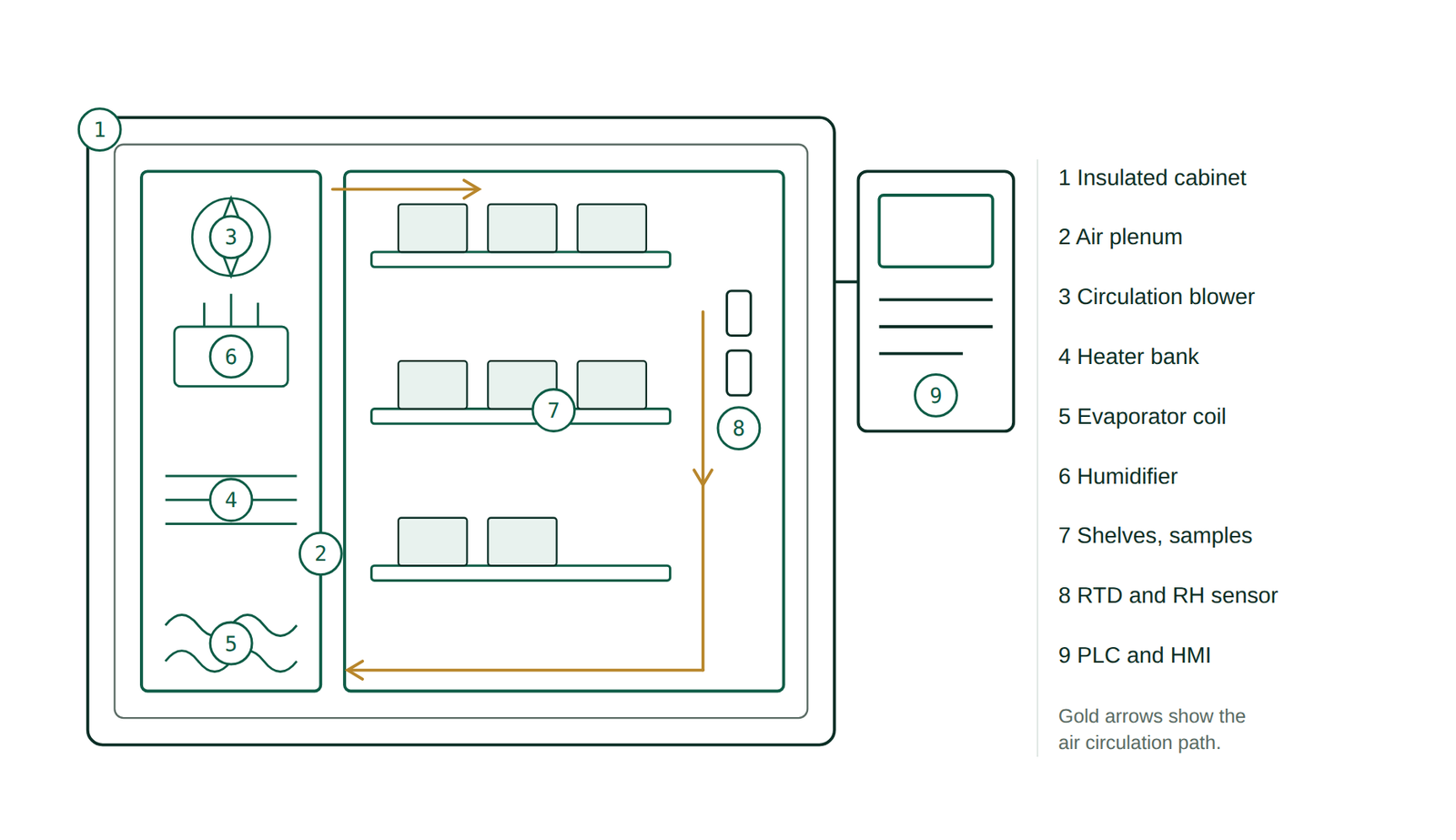
Component specification and failure table
| # | Component | Function | Typical specification | Common failure |
|---|---|---|---|---|
| 1 | Insulated cabinet | Limits heat and moisture exchange with the room | Rigid polyurethane foam, stainless inner liner | Gasket compression set, giving a cold or dry band near the door |
| 2 | Air plenum | Carries conditioned air past heater, coil and humidifier before it enters the working space | Baffled side duct, full cabinet height | Blocked baffle after a shelf is repositioned, producing a stratified chamber |
| 3 | Circulation blower | Moves the whole chamber volume continuously so every shelf sees the same air | Continuous-duty fan, interlocked with the controller | Bearing wear; uniformity drifts long before the fan stops |
| 4 | Heater bank | Adds sensible heat under PID control | Finned or cartridge elements, PID-trimmed | Element failure on one phase, seen as a slow ramp and a low-side offset |
| 5 | Evaporator coil | Removes heat, and removes moisture by condensing it below dew point | Direct-expansion coil with hot-gas or reheat control | Icing at low set points, which stops dehumidification entirely |
| 6 | Humidifier | Adds moisture to reach the RH set point | Steam generator or ultrasonic mist, fed from a water reservoir | Scale on the element; reservoir run dry, giving a slow RH decay |
| 7 | Perforated shelves | Support samples without blocking the air path | Perforated stainless, loading limit set at qualification | Overloading or solid trays, which defeats the mapping the chamber was qualified on |
| 8 | RTD and RH sensor | Provide the controlled variable to the PLC | Pt100 or Pt1000 RTD plus a capacitive RH element, in the return air | RH element drift and contamination; drift is invisible without independent calibration |
| 9 | PLC and HMI | Runs PID loops, logs data, raises alarms | PLC with audit-trailed data logging check source | Local-only logging with no back-up, so a power loss erases the excursion record |
Specifications in this table are typical equipment practice, not compendial requirements. Verify against your chamber’s own design qualification and the manufacturer’s documentation.
The control logic is worth stating once, because it explains most alarm behaviour. Temperature and humidity are not independent. Cooling the air to condense moisture also lowers its temperature, so a chamber holding 40 °C / 75 % RH is very often heating and cooling and humidifying at the same time, with the PID loops trading against each other. This is why a chamber recovers more slowly after a door opening at high-humidity set points than at 25 °C / 60 % RH, and why recovery time belongs in operational qualification rather than in the daily log.
Stability chamber qualification: DQ, IQ, OQ and PQ
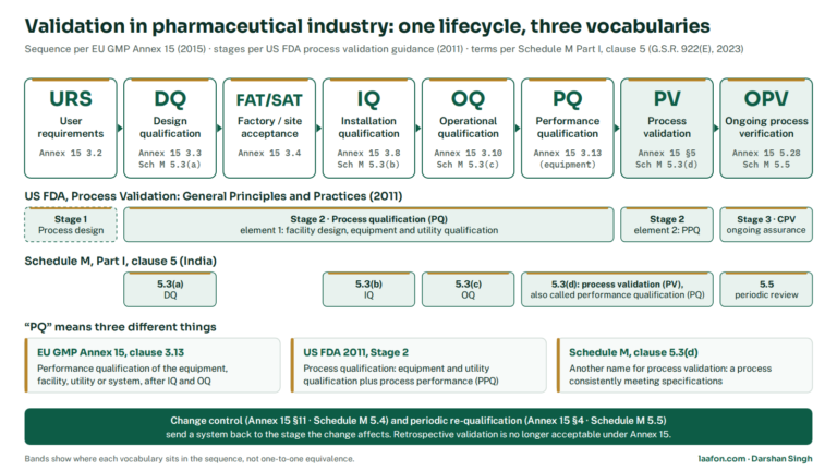
The four-stage model and its wording come from GMP, not from the stability guidelines. EudraLex Volume 4 Annex 15 defines each stage, and the definitions are short enough to quote in a protocol[5].
Design Qualification. Annex 15: “the documented verification that the proposed design of the facilities, systems and equipment is suitable for the intended purpose”[5]. For a stability chamber this is where the set points you will actually run are fixed against a user requirement specification, along with capacity, the number of shelves, sensor count, alarm routing and back-up power. Choosing the chamber before writing the URS is the most common reason a chamber cannot hold the condition a protocol later demands.
Installation Qualification. Annex 15: “the documented verification that the facilities, systems and equipment, as installed or modified, comply with the approved design and the manufacturer’s recommendations”[5]. Annex 15 also requires that IQ include calibration of instruments and the collection of supplier documentation. In practice: model and serial numbers, utility connections, drain and water feed, sensor certificates, and the manuals filed where an auditor can reach them.
Operational Qualification. Annex 15: “the documented verification that the facilities, systems and equipment, as installed or modified, perform as intended throughout the anticipated operating ranges”, with tests confirming operating limits under worst-case conditions[5]. For a chamber this is the empty-chamber work: uniformity and stability at each set point you will run, door-open recovery, power-failure recovery, and alarm challenge at the high and low limits.
Performance Qualification. Annex 15: “the documented verification that systems and equipment can perform effectively and reproducibly based on the approved process method and product specification”, normally after IQ and OQ and using worst-case loading[5]. For a chamber that means loaded mapping at maximum and minimum load, held long enough to cover a defrost cycle. Annex 15 requires that where re-qualification is done at intervals, the period is justified and the criteria defined; it does not name an interval[5].
Mapping: what is required, and what is only convention
This is worth stating precisely, because it is where published guidance and published blog posts diverge most.
No ICH stability guideline and no WHO stability annex requires temperature and humidity mapping of a stability chamber. The full text of ICH Q1A(R2) and of WHO’s stability annex was searched for mapping, qualification, calibration, alarm and back-up power. ICH Q1A(R2) addresses study design and does not address the equipment. WHO’s annex says only that the equipment must be capable of holding the condition and that conditions must be monitored and recorded[2].
The mapping requirement is real, but it is inherited. It comes from the GMP qualification expectation in Annex 15, where OQ must demonstrate performance “throughout the anticipated operating ranges” and PQ must use worst-case loading[5]. You cannot demonstrate either without measuring more than one point in the chamber. Stating it that way in a protocol is stronger than citing an ICH clause that does not exist, and it survives the auditor who asks where the requirement comes from.
| Mapping parameter | Common practice | Status |
|---|---|---|
| Sensor count, reach-in chamber | 9 sensors, 3 x 3 array | check source industry convention, fix in your protocol |
| Sensor count, walk-in room | More, scaled to volume | check source no compendial number exists |
| Study duration | Long enough to cover a defrost cycle | check source justify in the protocol |
| Uniformity acceptance | Every sensor inside the stated tolerance | derived tolerance is part of the ICH condition [1] |
| Loaded and empty runs | Empty at OQ, worst-case load at PQ | GMP Annex 15 [5] |
The only acceptance criterion here with a citable source is the last-but-one row, and it is derived rather than stated: if the storage condition is 25 °C ± 2 °C, no mapping sensor may sit outside 23 to 27 °C. Sensor counts and tighter internal limits are your site’s decision and should be justified in the protocol, not attributed to ICH.
Excursions, alarms and the 24-hour rule
There is one hard, citable rule for excursions in a stability study, and it is in WHO’s annex rather than in ICH Q1A(R2). Short-term changes from opening the door are accepted as unavoidable. Beyond that: “the effect of excursions due to equipment failure should be assessed, addressed and reported if judged to affect stability results. Excursions that exceed the defined tolerances for more than 24 hours should be described in the study report and their effects assessed.”[2]
Two consequences follow, and both belong in the SOP rather than in a guideline summary.
- Your monitoring interval has to be short enough to resolve 24 hours. A logger reading once an hour does this comfortably; a manual twice-daily chart reading does not, because you cannot show when an excursion started.
- Alarm routing has to reach someone outside working hours. A failure at 18:00 on a Friday crosses 24 hours before Monday. This is an operational design decision, not a compliance formality, and it is the single most common finding on stability chambers in audits reported by consultants. Confirm your own alarm escalation against your site’s out-of-hours cover.
Calibration and monitoring: standard versus site policy
There is no compendial or ICH calibration interval for a stability chamber. Annex 15 requires calibration of instruments as part of IQ and requires that any periodic re-qualification interval be justified, but it names no frequency[5]. 21 CFR 211.166 names none[3]. WHO’s annex names none[2].
So an annual calibration interval is a site policy decision, and it must be written and justified as one. The honest justification is usually a combination of sensor manufacturer drift data, the chamber’s own history of calibration results, and the consequence of an undetected drift, which for a stability chamber is the loss of an entire study. Where a page tells you that annual calibration is an ICH requirement, it is wrong, and an auditor who knows that will discount everything else on the page.
If you are equipping or re-equipping a QC laboratory, the same standard-versus-policy distinction runs through every instrument in it. The pH meter calibration procedure and the Karl Fischer titration and calibration procedure on this site work through the same question for two instruments where the pharmacopoeias do give limits, which makes a useful contrast with the chamber, where they do not.
SOP for stability chamber operation and monitoring
1. Purpose
To define the operation, loading, monitoring, excursion handling and record-keeping for a stability chamber in pharmaceutical industry quality control, used to hold samples under a defined storage condition.
2. Scope
Applies to all qualified reach-in and walk-in stability chambers in the Quality Control stability area, for long-term, intermediate, accelerated, refrigerated and frozen storage conditions. This procedure does not cover photostability chambers, which are covered by a separate procedure because the exposure requirement in ICH Q1B is expressed in lux hours and near-ultraviolet energy rather than as a held temperature and humidity[6]. It also does not cover chamber qualification or mapping, which are covered by the validation protocol.
3. Responsibility
- Analyst / Operator, QC: daily verification, loading and unloading, log entries, first response to an alarm.
- Officer, Quality Control: review of logs and trend data, initiation of the deviation record, coordination of engineering response.
- Engineering: corrective maintenance, refrigeration and humidifier service, back-up power.
- Head, Quality Assurance: approval of this procedure, approval of excursion assessments and impact decisions, periodic review.
4. Materials and equipment
- Qualified stability chamber with PLC control and audit-trailed data logging.
- Independent calibrated reference thermometer and hygrometer, with valid calibration certificates traceable to a national standard.
- Purified water for the humidifier reservoir, of the grade named in the manufacturer’s manual.
- Stability sample trays, sample register, and Annexure-I daily log format.
5. Procedure
6. Acceptance criteria
| Parameter | Limit | Basis |
|---|---|---|
| Long-term condition, 25 °C track | 25 °C ± 2 °C / 60 % RH ± 5 % RH | ICH Q1A(R2) [1] |
| Intermediate condition | 30 °C ± 2 °C / 65 % RH ± 5 % RH | ICH not used on the 30 °C track [1] |
| Accelerated condition | 40 °C ± 2 °C / 75 % RH ± 5 % RH | ICH Q1A(R2) [1] |
| Refrigerated condition | 5 °C ± 3 °C | ICH Q1A(R2) [1] |
| Frozen condition | -20 °C ± 5 °C | ICH Q1A(R2) [1] |
| Reportable excursion | Outside tolerance for more than 24 h | WHO stability annex [2] |
| Monitoring interval | Continuous logging, manual check twice daily | site policy not a compendial requirement |
| Calibration interval | Site-defined and justified | site policy no compendial interval exists [5] |
| Mapping sensor count | Site-defined and justified | check source no compendial number exists |
Swipe the table sideways on a phone. Rows marked site policy or check source are internal convention, not pharmacopoeial or ICH requirements, and must be justified in your own protocol.
7. Frequency
- Continuous: automatic logging of temperature and relative humidity, with alarms routed to a monitored point. site policy
- Twice per working day: manual verification and Annexure-I entry against the independent reference instrument. site policy
- Weekly: humidifier reservoir and drain check, trend review by the Officer, QC. site policy
- Per protocol: sample pull at the scheduled interval, which for a long-term study of a 12-month or longer shelf life is every three months in year one, every six months in year two, and annually thereafter. WHO [2]
- At a justified interval: calibration and re-qualification, period defined and justified in the validation master plan. GMP Annex 15 [5]
8. Precautions
- Never restore a chamber after a failure and continue the study without a documented impact assessment. A chamber that reads correctly again tells you nothing about the hours it did not.
- Never adjust a set point to bring a reading inside tolerance. The set point belongs to the protocol.
- Never rely on the chamber’s own display as the record of record where an independent calibrated reference is required by the procedure.
- Do not defeat or bypass the door alarm during a long loading operation without recording it.
- Electrical and refrigerant work is engineering work. Isolate before opening the machinery compartment.
9. Deviation handling
- Record the observation, the time first observed and the reading, before taking corrective action.
- Establish from the logger record when the excursion began and when it ended. This, not the time of observation, is the duration that matters.
- Where the excursion exceeded the tolerance for more than 24 hours, describe it in the study report and assess its effect, in line with the WHO annex[2].
- Where the excursion arose from equipment failure, assess and address the effect on the stability results regardless of duration[2].
- Raise a deviation record. Include the affected protocols, batches and pull points, not only the chamber.
- Head QA decides on the disposition of the affected samples and whether the study can continue.
10. Annexure-I: Stability chamber daily monitoring record
| Date | Time | Chamber ID | Set point | HMI temp | HMI RH | Ref temp | Ref RH | Within limit | Done by | Checked by |
|---|---|---|---|---|---|---|---|---|---|---|
Copies as tab-separated text, so it pastes straight into a spreadsheet column layout.
11. Other annexures
- Annexure-II: Stability sample register (protocol, batch, condition, date in, pull schedule).
- Annexure-III: Excursion and deviation record.
- Annexure-IV: Chamber calibration status register.
12. Revision history
| Version | Effective | Change | Reason |
|---|---|---|---|
| 00 | DD-MMM-YYYY | New procedure | Initial issue |
| 01 | DD-MMM-YYYY | Added 24-hour excursion reporting rule and independent reference check | Alignment with the WHO stability annex |
What changes when ICH Q1 replaces Q1A(R2)
Q1A(R2) has been the operative guideline since 6 February 2003[1]. It is being replaced. ICH has consolidated the Q1A(R2), Q1B, Q1C, Q1D, Q1E and Q5C series into a single guideline, Q1 Stability Testing of Drug Substances and Drug Products, which also extends coverage to advanced therapy medicinal products, vaccines and other complex biological products that the 1996 to 2004 series did not address[7].
Where it stands as of this update. The Q1 expert working group signed off Step 1 and the ICH Assembly endorsed Step 2a and 2b in April 2025, and the Step 3 public consultation ran from April to September 2025[8]. FDA published the draft in the US in June 2025 under docket FDA-2025-D-1106, marked “Draft – Not for implementation”[7]. The working group’s published work plan projects Step 4 adoption in November 2026[8].
What that means for a chamber and its SOP, stated conservatively. Until Step 4 adoption and regional implementation, Q1A(R2) remains the guideline your protocol cites, and the seven conditions in the table above are unchanged. The practical preparation is documentary rather than physical: know which of your protocols cite Q1A(R2), Q1B, Q1D or Q1E by number, because those citations will need review, and check the consultation draft against the storage conditions you have qualified before assuming they carry over. This page will be updated when Step 4 is reached.
Reviewing a stability programme before an inspection
If your stability protocols, chamber qualification records and excursion assessments need to be read against current expectations before an audit, that document review is what Laafon Galaxy’s pharmaceutical regulatory compliance consultation covers. If the question is instead how much a compliant QC and stability area costs to build, the pharma plant setup cost calculator gives an indicative figure by block.
Frequently asked questions
A blower circulates air continuously through a side plenum containing a heater bank, a refrigeration evaporator coil and a humidifier. A PLC running PID loops trims each element against a temperature sensor and a humidity sensor mounted in the return air, so the whole working volume is held inside the tolerance stated in the storage condition. Temperature and humidity are coupled, because condensing moisture on the coil also cools the air, which is why a chamber at 40 °C and 75 % RH is frequently heating, cooling and humidifying at the same time.
For drug products, ICH Q1A(R2) gives long term at 25 °C plus or minus 2 °C with 60 % RH plus or minus 5 % RH, or 30 °C plus or minus 2 °C with 65 % RH plus or minus 5 % RH as an alternative; intermediate at 30 °C plus or minus 2 °C with 65 % RH plus or minus 5 % RH; and accelerated at 40 °C plus or minus 2 °C with 75 % RH plus or minus 5 % RH. Refrigerated products run long term at 5 °C plus or minus 3 °C with accelerated at 25 °C plus or minus 2 °C and 60 % RH plus or minus 5 % RH. Frozen products run long term at minus 20 °C plus or minus 5 °C. If the 30 °C long-term track is chosen, there is no intermediate condition.
No. Neither ICH Q1A(R2) nor the WHO stability annex requires mapping of a stability chamber; they address study design and require only that the equipment be capable of holding the condition and that conditions be monitored and recorded. The mapping expectation comes from GMP qualification, where operational qualification must demonstrate performance throughout the anticipated operating ranges and performance qualification must use worst-case loading. Cite the GMP qualification requirement in your protocol rather than an ICH clause, because the ICH clause does not exist.
There is no compendial or ICH calibration interval for a stability chamber. EU GMP Annex 15 requires calibration of instruments as part of installation qualification and requires that any periodic re-qualification interval be justified, but names no frequency; 21 CFR 211.166 and the WHO stability annex name none either. An annual interval is therefore a site policy decision that must be written and justified, normally from sensor drift data, the chamber’s own calibration history and the consequence of an undetected drift.
WHO’s compilation of conditions confirmed by Member States, updated March 2021, records India’s confirmed long-term testing condition as 30 °C and 70 % RH. Much of the Indian industry runs 30 °C and 75 % RH, the WHO Zone IVB condition, which is more demanding on humidity and will generally support the less demanding condition. Since ICH Q1F was withdrawn there is no single global authority assigning countries to climatic zones, so confirm the condition required for your own regulatory pathway before writing a set point into a protocol.
The WHO stability annex sets the reportable threshold at 24 hours: excursions that exceed the defined tolerances for more than 24 hours should be described in the study report and their effects assessed. Short-term changes from opening the door are accepted as unavoidable. Separately, and with no duration threshold, the effect of any excursion arising from equipment failure should be assessed, addressed and reported if judged to affect the stability results.
Related on Laafon
- ICH guidelines: the quality, safety and efficacy series explained
- pH meter principle, working and calibration procedure
- Karl Fischer titration and calibration procedure
- Gas chromatography: residual solvent testing under ICH Q3C
- CDSCO revised Schedule M compliance dashboard
- USFDA pre-approval inspection checklist
- All standard operating procedures on Laafon
References
- International Council for Harmonisation. ICH Q1A(R2): Stability Testing of New Drug Substances and Products. Step 4 version, 6 February 2003. Available from: https://database.ich.org/sites/default/files/Q1A(R2)%20Guideline.pdf. Accessed September 2026.
- World Health Organization. Stability testing of active pharmaceutical ingredients and finished pharmaceutical products. WHO Technical Report Series No. 1010, Annex 10, 2018. Available from: https://database.ich.org/sites/default/files/Q1F_Stability_Guideline_WHO_2018.pdf. Accessed September 2026.
- US Food and Drug Administration. 21 CFR 211.166: Stability testing. Code of Federal Regulations, Title 21, Part 211, Subpart I. Available from: https://www.ecfr.gov/current/title-21/chapter-I/subchapter-C/part-211/subpart-I/section-211.166. Accessed September 2026.
- World Health Organization. Stability conditions for WHO Member States by Region. Update March 2021. Available from: https://cdn.who.int/media/docs/default-source/medicines/norms-and-standards/guidelines/regulatory-standards/trs953-annex2-appendix1-stability-conditions-table-2018.pdf. Accessed September 2026.
- European Commission. EudraLex Volume 4, Annex 15: Qualification and Validation. October 2015. Available from: https://health.ec.europa.eu/system/files/2016-11/2015-10_annex15_0.pdf. Accessed September 2026.
- International Council for Harmonisation. ICH Q1B: Photostability Testing of New Drug Substances and Products. Step 4 version, 6 November 1996. Available from: https://database.ich.org/sites/default/files/Q1B%20Guideline.pdf. Accessed September 2026.
- US Food and Drug Administration. Q1 Stability Testing of Drug Substances and Drug Products. Draft guidance for industry, June 2025. Docket FDA-2025-D-1106. Available from: https://www.fda.gov/regulatory-information/search-fda-guidance-documents/q1-stability-testing-drug-substances-and-drug-products. Accessed September 2026.
- International Council for Harmonisation. ICH Q1 Expert Working Group Work Plan. 11 February 2026. Available from: https://database.ich.org/sites/default/files/ICH52_Q1_EWG_WorkPlan_2026_0318.pdf. Accessed September 2026.
The procedure above is a template for adaptation. It requires local qualification, validation and Quality Assurance approval before use, and every acceptance criterion must be verified against the current pharmacopoeial edition and guideline version applicable at your site. Guideline texts and Indian statutory instruments change between editions, and ICH Q1A(R2) is itself under revision. Technical and educational content only, not medical, legal or regulatory advice.