
There is no current WHO or EU GMP requirement for 20 air changes per hour. The figure everyone quotes comes from WHO Technical Report Series 961, Annex 5 (2011), clause 4.1.6, where it reads “could normally vary between 6 and 20 air changes per hour” — a typical range, in a document that states it is “not intended to be prescriptive in specifying requirements and design parameters” [1]. That annex has since been superseded by TRS 1010, Annex 8 (2018), which contains no numeric air-change rate at all [2].
What that means in practice for an HVAC system in pharmaceutical industry facilities is that your air-change rate is a number you must derive and defend from your own room classification, heat and particulate load, and recovery testing — not a number you can copy from a guideline. The three figures the current texts do give are a pressure differential of minimum 10 Pa between adjacent grades, a clean-up period of less than 20 minutes, and HEPA filtration of at least EN 1822 class H13. Each is sourced in the table below.
The 20 air changes per hour rule does not exist
Open almost any Indian pharmaceutical User Requirement Specification and you will find a line reading “20 ACPH as per WHO”. It is one of the most widely repeated numbers in the industry, and it does not survive contact with the source document.
The number originates in WHO Technical Report Series No. 961 (2011), Annex 5, at clause 4.1.6. The full sentence reads: “Air change rates are normally determined by the following considerations (could normally vary between 6 and 20 air changes per hour):” — and it introduces a list of ten factors the designer must weigh [1]. Three things follow from reading it in place rather than quoting the parenthesis alone:
- It is a range, not a target. Six is as much “per WHO” as twenty. Specifying the top of a range as a fixed set point is a design decision, not a compliance one, and it carries an energy and capital cost that has to be justified somewhere.
- It is descriptive, not prescriptive. The wording is “could normally vary”. The same annex says at clause 4.1.5 that “The air change rates should be determined by the manufacturer and designer, taking into account the various critical parameters using a risk based approach”, and section 2 states the guidelines are “not intended to be prescriptive in specifying requirements and design parameters” [1].
- The edition is superseded. TRS 961 Annex 5 was replaced by TRS 1010, Annex 8 (2018). Searching the current annex in full for “air change”, “air-change”, “ACH”, “changes per hour” and “air exchange” returns no numeric value anywhere. Air change rate survives only as a glossary definition and as a bullet in clause 12.8’s list of parameters needing alert and action limits [2].
Why this matters in an audit. An inspector who asks “how did you arrive at this air change rate?” is not asking you to recite a guideline. Citing a superseded, non-prescriptive range as the basis for a design parameter is a weaker answer than showing a recovery test result, a heat-load calculation and a particulate challenge that together justify the number you chose. The current texts move the burden of proof onto your qualification data, and that is the substantive change between the 2011 and 2018 editions.
What the guidelines actually specify for an HVAC system in pharmaceutical industry cleanrooms
The table below is built from the primary documents, opened and searched rather than summarised. Where a figure could not be read first-hand in the source, the row carries a check source badge instead of a number. A correct gap is more useful to you than a plausible wrong figure.
| Parameter | WHO TRS 961 Annex 5 (2011, superseded) | WHO TRS 1010 Annex 8 (2018, current) | EU GMP Annex 1 (2022) |
|---|---|---|---|
| Air changes per hour | “could normally vary between 6 and 20 air changes per hour” — cl. 4.1.6, indicative range [1] | No numeric value. Concept only, cl. 4.6 and cl. 12.8 [2] | No numeric value in the classification and qualification clauses; not among the nine qualification elements at cl. 4.25 [3] |
| Pressure differential, adjacent areas | 15 Pa “often used”; 5–20 Pa “may be acceptable” — cl. 4.7.4 [1] | No value. “individually assessed according to the products handled” — cl. 7.4 [2] | Minimum 10 Pa (guidance value) between adjacent grades — cl. 4.14 verified [3] |
| Clean-up / recovery period | “generally of the order of 20 minutes” — cl. 4.1.10 [1] | No value. “within the specified time” — cl. 5.8 [2] | Less than 20 minutes (guidance value) — cl. 4.29 iii [3] |
| Unidirectional airflow velocity | 0.36 to 0.54 m/s guidance — cl. 4.3.4 [1] | Out of scope (non-sterile products) [2] | check source cl. 4.30 — read the clause directly; the 2007 figure of 0.45 m/s is not retained [3] |
| Cleanliness classification | Protection-level tables [1] | Defers to ISO 14644 — cl. 12.4 [2][6] | Table 1, Grades A–D — cl. 4.27. Grade A and B at rest: 3 520 particles ≥0.5 µm/m³ [3] |
| HEPA filter grade | EN 779 / EN 1822 class tables [1] | “at least H13 or equivalent”, EN 1822 — cl. 6.2 [2] | Integrity testing required as a qualification element — cl. 4.25 i [3] |
| Requalification interval | Not stated as a fixed period [1] | Risk-based, no fixed period — cl. 12.9 [2] | check source cl. 4.32 — read the clause directly before writing it into a schedule [3] |
| Temperature and relative humidity | check source cl. 4.9 [1] | No numeric values. Qualitative only — cl. 8.1 to 8.4 [2] | Temperature and RH tests listed as qualification elements — cl. 4.25 [3] |
Swipe the table sideways on a phone. A check source badge means the clause exists and is named, but the figure was not read first-hand from the primary document during preparation of this page — open the clause yourself rather than taking a number from any secondary summary, this one included.
One nuance worth carrying into your specification. In Annex 1’s Table 1, Grade A and Grade B at rest carry the note “Not specified” against the ≥5 µm column, with a footnote that classification including 5 µm particles “may be considered where indicated by the CCS or historical trends” [3]. “Not specified” is not the same as zero, and a specification written as “zero 5 µm particles in Grade A” is unachievable as written and will generate deviations you cannot close.
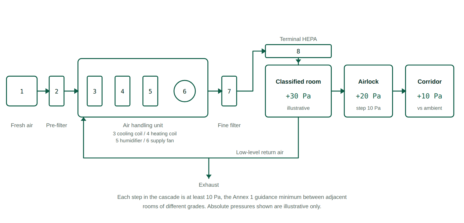
Air path and pressure cascade in a pharmaceutical cleanroom
Tap or click any numbered part of the schematic to read its function, the specification that governs it, and the failure mode that most often shows up in qualification.
Select a numbered part
Tap any numbered component in the schematic to see what it does, what governs its specification, and how it typically fails in qualification.
Schedule M status in India as of September 2026
India’s revised Schedule M was notified by G.S.R. 922(E), dated 28 December 2023, published in the Gazette of India Extraordinary on 5 January 2024 under gazette identifier CG-DL-E-05012024-251166 [4]. The distinction between the two dates is not pedantry: the implementation clock in rule 6 of the Drugs (Amendment) Rules, 2023 runs from the date of publication, not the date of the notification.
The compliance timeline was then extended once, by G.S.R. 127(E) dated 11 February 2025 — the Drugs Amendment Rules, 2025. That instrument allows manufacturers with “turnover less than two hundred and fifty crores” to apply in Form A, within three months of publication, for an extension of the implementation timeline “till 31st day of December, 2025” [5]. Note the enacted wording: the draft at G.S.R. 10(E) had read “of or less than two hundred and fifty crores”, so a manufacturer at exactly ₹250 crore sits inside the draft and outside the final text.
Form A of that notification is also the clearest primary-source statement that HVAC is an express compliance element of the revised Schedule M: its upgradation gap analysis enumerates “(iv) HVAC system,” alongside plant, equipment, laboratory equipment and utilities [5].
Current position, and the limit of what can be verified. CDSCO’s own gazette notifications register was read on 19 September 2026 and is current to 8 September 2026. It carries four Schedule M instruments in total — G.S.R. 922(E), G.S.R. 10(E), G.S.R. 11(E) and G.S.R. 127(E) — and no further extension notified during 2026 [7]. On the face of the Government’s own register, the extended deadline of 31 December 2025 has therefore expired and revised Schedule M applies to all manufacturers. Two caveats belong on that statement: the CDSCO register is a curated index rather than the Gazette of India itself, and an extension granted by circular or public notice rather than by gazette notification would not appear there. Verify against the Gazette before relying on this for a filing.
The numeric HVAC parameters inside revised Schedule M — air-change rates, pressure differentials, grade tables, HEPA grades, temperature and humidity limits — are deliberately not reproduced on this page. The English text of the relevant Part could not be retrieved from CDSCO, the India Code portal or any state FDA during preparation, and publishing figures that have not been read in the instrument itself is exactly the error this page exists to argue against. Read them in the gazette PDF directly [4]. If you are assessing a facility against them, our Schedule M plant area requirements guide and the 50-point GMP due diligence checklist cover the adjacent requirements that are verifiable.
Which qualification tests does your room need?
SOP: HVAC system qualification and periodic requalification
The block below is a working template covering qualification of an HVAC system in pharmaceutical industry premises, classified and controlled. It is written to be adapted, not adopted — the header fields are deliberately blank because inventing a document number for someone else’s quality system is worse than leaving a gap.
1. Purpose
To define the procedure for qualification and periodic requalification of the heating, ventilation and air-conditioning system serving classified and controlled manufacturing areas, and to establish the documented basis for the air-change rate, pressure cascade and filtration specification adopted at the site.
2. Scope
Applies to all air handling units, terminal filtration, ducting, dampers and associated control instrumentation serving classified production, packing and quality control areas. It does not cover process utilities such as compressed air, purified water or nitrogen; it does not cover comfort-only air conditioning in administrative areas; and it does not cover laminar airflow benches and biosafety cabinets qualified under their own equipment procedures.
3. Responsibility
- Engineering Officer: executes installation and operational checks, maintains the system drawings, filter register and damper settings.
- Officer, Quality Control: performs particle counts, microbial air and surface sampling, and recovery testing.
- Validation Officer: prepares the protocol, compiles the report, and maintains the qualification status matrix.
- Head, Quality Assurance: approves the protocol and report, approves deviations, and authorises release of the area for use.
4. Materials and instruments
- Calibrated airborne particle counter, sampling at a flow rate stated in the protocol, with a current calibration certificate.
- Calibrated anemometer or balometer for velocity and volumetric flow measurement.
- Calibrated differential pressure gauge or manometer, with a resolution finer than the smallest differential being demonstrated.
- Aerosol photometer and aerosol generator for installed filter leakage testing, with the challenge medium named in the protocol.
- Calibrated thermohygrometer; settle plates and contact plates of the media and diameter stated in the environmental monitoring procedure.
- Airflow visualisation equipment where unidirectional airflow is claimed.
5. Procedure
6. Acceptance criteria
| Parameter | Criterion | Basis |
|---|---|---|
| Differential pressure, adjacent grades | Minimum 10 Pa | guidance value EU GMP Annex 1 cl. 4.14 [3] |
| Clean-up period to at-rest limits | Less than 20 minutes | guidance value EU GMP Annex 1 cl. 4.29 iii [3] |
| Total particles, Grade A and B at rest, ≥0.5 µm | 3 520 per m³ | compendial EU GMP Annex 1 Table 1, cl. 4.27 [3] |
| Total particles, Grade C at rest, ≥0.5 µm | 352 000 per m³ | compendial EU GMP Annex 1 Table 1, cl. 4.27 [3] |
| Total particles, Grade D at rest, ≥0.5 µm | 3 520 000 per m³ | compendial EU GMP Annex 1 Table 1, cl. 4.27 [3] |
| Terminal filter grade for cross-contamination control | At least H13, EN 1822 | guideline WHO TRS 1010 Annex 8 cl. 6.2 [2] |
| Air changes per hour | Site-derived and justified | site policy no numeric requirement in the current texts [1][2][3] |
| Unidirectional airflow velocity | check source | EU GMP Annex 1 cl. 4.30 — read the clause before setting the limit [3] |
| Requalification interval | check source | EU GMP Annex 1 cl. 4.32 for grade-wise maxima [3]; risk-based under WHO cl. 12.9 [2] |
| Temperature and relative humidity | Site-derived per product and comfort | site policy no numeric limits in WHO TRS 1010 Annex 8 cl. 8.1 to 8.4 [2] |
Rows marked site policy are internal convention, not a compendial or statutory requirement. Rows marked check source point you at the governing clause instead of giving a number that was not read first-hand.
7. Frequency
Initial qualification before first manufacturing use. Requalification at the interval established in the site validation master plan, and additionally after any change assessed as impacting the system through change control. WHO TRS 1010 Annex 8 clause 12.9 sets no fixed period, requiring instead that the frequency be established on risk, facility type, level of product protection and the extent of routine ongoing monitoring [2]. Where the site supplies EU markets, read the grade-wise maximum intervals at Annex 1 clause 4.32 directly and adopt the shorter of the two.
8. Precautions
- Do not perform pressure measurement with a door held open or with an adjacent air handling unit switched off; both produce a passing result that will not reproduce.
- Do not classify a room using a particle counter whose calibration expires during the study.
- Record the operational state, at rest or in operation, against every particle result. A result with no state recorded cannot be assessed against Table 1 and will be raised as a documentation observation.
- Where a terminal filter is repaired rather than replaced, record the repair location and area, and confirm the repair is within the filter manufacturer’s stated allowance.
- Periodic switching off of air handling units carries a contamination risk that must be assessed before it is adopted as an energy measure (cl. 5.16) [2].
9. Deviation handling
Where any acceptance criterion is not met, raise a deviation before further testing, quarantine the area from manufacturing use, and investigate to root cause. Assess product manufactured in the area since the last passing result. Do not re-test to a passing result without a documented, approved investigation explaining why the first result is invalid — an unexplained re-test is the single most commonly cited finding on environmental qualification records.
10. Annexure-I: HVAC qualification test record
| Date | Room / AHU ID | Test | Instrument ID | Result | Limit | Pass / Fail | Done by | Checked by |
|---|---|---|---|---|---|---|---|---|
11. Revision history
| Version | Effective | Change | Reason |
|---|---|---|---|
| 00 | DD-MMM-YYYY | First issue | New system |
| 01 | DD-MMM-YYYY | Air-change basis moved from cited guideline value to site-derived justification | Guideline edition superseded |
Working principle of the air handling unit
The working principle of an HVAC system is heat transport: it moves thermal energy out of a space that must stay cool into a medium that can carry it away. What distinguishes an HVAC system in pharmaceutical industry use from a commercial one is that the same plant simultaneously controls particulate, humidity and pressure, and all four are set inside the air handling unit.
Air entering the unit is drawn through a pre-filter that protects the coils from coarse debris. It then passes the cooling coil, where sensible heat is removed and, below the dew point, moisture condenses out — which is how a cooling coil dehumidifies as a side effect of cooling. A heating coil downstream reheats the now over-cooled, dry air to the supply temperature required, and a humidifier adds moisture back where the room specification demands a minimum relative humidity. The supply fan provides the static pressure needed to push that air through the fine filter, the duct run, the terminal HEPA and the room itself, and back through the return path.
Two design decisions separate a pharmaceutical unit from a comfort one. The first is the pressure cascade: supply and return volumes are deliberately unbalanced room by room so that each classified space sits above its neighbour, and air always moves from cleaner to less clean at every opening. The second is the recirculation decision — how much return air is reused against how much is exhausted. WHO TRS 1010 Annex 8 addresses both full fresh air and recirculation systems and permits HEPA filtration in either the supply or the return air stream to control cross-contamination, requiring at least EN 1822 class H13 where filters are used for that purpose [2]. For products handling hazardous substances, the direction of that assessment reverses and separate guidance applies.
The single most common qualification failure in this arrangement is not a component fault. It is a cascade that was set up with the doors of an adjacent suite closed and a neighbouring unit running, and which collapses when normal operations resume. Measuring the cascade in the state the room will actually be used in is what step 5.7 above exists to force. Our guide to aseptic processing control and contamination prevention covers the downstream consequences when it fails in a sterile area.
Assessing a facility against Schedule M or Annex 1?
Laafon Galaxy Pharmaceuticals carries out regulatory gap assessments covering cleanroom classification, HVAC qualification documentation and Schedule M readiness, for both existing plants and facilities under design. If you need the air-change basis, cascade design and qualification record set reviewed before an inspection, our pharmaceutical regulatory compliance consultation is the route in. Facilities still at the design stage may find the pharma plant setup cost calculator a useful starting point for scoping the HVAC package.
Frequently asked questions
No. The figure comes from WHO TRS 961 Annex 5 (2011) clause 4.1.6, where it is the upper end of a range described as what air change rates “could normally vary between”, in a document that says it is not intended to be prescriptive. That annex was superseded by TRS 1010 Annex 8 (2018), which gives no numeric air-change rate at all, and EU GMP Annex 1 (2022) does not specify one in its classification and qualification clauses either. Your rate must be derived from your own room classification, load and recovery data and defended on that basis.
EU GMP Annex 1 (2022) clause 4.14 states that adjacent rooms of different grades should have an air pressure difference of a minimum of 10 Pascals, expressed as a guidance value. The superseded WHO TRS 961 Annex 5 clause 4.7.4 said 15 Pa was often used with 5 to 20 Pa acceptable; the current WHO TRS 1010 Annex 8 gives no number and requires the differential to be individually assessed according to the products handled. Where a site supplies EU markets, the 10 Pa minimum is the one to design the cascade against.
They describe the same phenomenon but the current texts use them differently, which is a common source of confusion in protocols. EU GMP Annex 1 clause 4.29 iii uses the term “clean up” period and attaches the number to it: the at-rest particle limits should be achieved after a clean-up period with a guidance value of less than 20 minutes. “Recovery test” appears separately in Annex 1’s qualification list at clause 4.25 with no number attached. WHO TRS 1010 Annex 8 treats clean-up as a synonym of recovery in its glossary and sets no time, requiring only that the specified time be achieved. Write whichever term your protocol uses consistently, and state the number you have qualified to.
This page does not answer that question, deliberately. The English text of the Part of revised Schedule M covering premises could not be retrieved from CDSCO, the India Code portal or any state FDA site during preparation, and a figure that has not been read in the instrument itself should not be published as a requirement. What is verifiable is that HVAC is an express compliance element: Form A of G.S.R. 127(E) enumerates “(iv) HVAC system,” in its upgradation gap analysis. Read the numeric requirements in the gazette PDF of G.S.R. 922(E) directly.
No, and specifying it that way creates deviations you cannot close. In Annex 1’s Table 1 at clause 4.27, both Grade A and Grade B at rest carry “Not specified” in the 5 micron column, with a footnote that classification including 5 micron particles may be considered where indicated by the contamination control strategy or by historical trends. Grade B in operation is 2 930 per cubic metre. “Not specified” is a deliberate change from the 2007 version and is not the same as a limit of zero.
No. Its scope section places sterile products, products containing hazardous substances and biological products outside the annex, directing them to separate WHO guidelines. It also defines no cleanliness classes of its own, cross-referring to ISO 14644 at clause 12.4 and leaving the selection of class to the manufacturer. For a sterile facility the governing environmental text is EU GMP Annex 1 or the equivalent in the target market, and the WHO annex is the non-sterile companion rather than a substitute.
Related on Laafon
- Aseptic processing control and contamination prevention — what the cascade protects, and what happens downstream when it fails.
- Pharma plant area requirements as per Schedule M — the room-area side of the same compliance exercise.
- USFDA compliance and inspection readiness guide — how environmental qualification records are examined in an inspection.
- WHO-GMP versus USFDA compliance — where the two frameworks diverge on facility expectations.
- SOP for dry powder filling operation, injectable vials — a sterile operation carried out inside the classified environment described here.
- All SOPs on Laafon — the full standard operating procedure library.
References
- World Health Organization. Supplementary guidelines on good manufacturing practices for heating, ventilation and air-conditioning systems for non-sterile pharmaceutical dosage forms. WHO Technical Report Series, No. 961, Annex 5. Geneva: WHO; 2011. Superseded. Available from: gmpsop.com hosted copy of TRS 961 Annex 5. Accessed September 2026.
- World Health Organization. Guidelines on heating, ventilation and air-conditioning systems for non-sterile pharmaceutical products. WHO Technical Report Series, No. 1010, Annex 8. Geneva: WHO; 2018. Available from: who.int. Accessed September 2026.
- European Commission. EudraLex Volume 4, Annex 1: Manufacture of Sterile Medicinal Products. C(2022) 5938 final. Brussels: European Commission; 22 August 2022. Available from: health.ec.europa.eu. Accessed September 2026.
- Ministry of Health and Family Welfare, Government of India. G.S.R. 922(E), dated 28 December 2023, notifying the revised Schedule M. The Gazette of India Extraordinary, Part II Section 3 Sub-section (i), published 5 January 2024. Available from: cdsco.gov.in. Accessed September 2026.
- Ministry of Health and Family Welfare, Government of India. G.S.R. 127(E), dated 11 February 2025. Drugs Amendment Rules, 2025. Available from: cdsco.gov.in. Accessed September 2026.
- International Organization for Standardization. ISO 14644-1:2015 Cleanrooms and associated controlled environments, Part 1: Classification of air cleanliness by particle concentration. Geneva: ISO; 2015. Available from: iso.org. Accessed September 2026.
- Central Drugs Standard Control Organisation. Gazette Notifications register. New Delhi: CDSCO. Available from: cdsco.gov.in. Register read 19 September 2026, current to 8 September 2026.
- Pharmaceutical Inspection Co-operation Scheme. PIC/S Guide to Good Manufacturing Practice for Medicinal Products, Annexes, PE 009. Geneva: PIC/S. Available from: picscheme.org. Accessed September 2026.
The standard operating procedure on this page is a template for adaptation. It requires local qualification, validation and Quality Assurance approval before use, and every acceptance criterion must be verified against the edition of the pharmacopoeial or regulatory text applicable at your site and in your target markets. Pharmacopoeial texts and Indian statutory instruments change between editions, and clause numbering changes with them. Rows marked check source name the governing clause precisely because the figure was not read first-hand during preparation of this page. Technical and educational content only; not medical, legal or investment advice.